Connections & first power-on
Identify each port before connecting cables. The rear panel shown here is the integrated cabinet in the Pro V1.0 manual; compare it with your delivered unit.
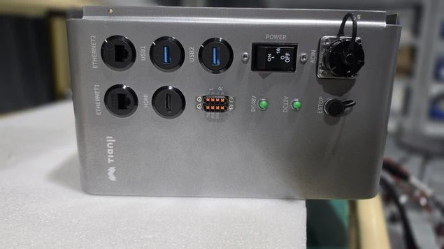
| Label | Connection |
|---|---|
| AC IN | Supplied mains power cable |
| ESTOP | Supplied E-stop harness |
| ETHERNET1 / ETHERNET2 | Ethernet connection to the host computer |
| USB1 / USB2 | USB peripherals |
| HDMI | Display |
| POWER | Main power switch |
Connect the supplied cables
With power off, connect the power cable to AC IN and turn its locking ring clockwise. Check that the supply matches the delivered system's rating; do not assume a U.S. unit accepts the brochure's AC 220 V supply without confirmation.
Connect the E-stop's 8-pin harness to ESTOP, aligning the connector's red mark with the port notch. Connect Ethernet from ETHERNET1 or ETHERNET2 to the host computer.
First power-on
After the pre-use checks and cable inspection, confirm the E-stop is released, then turn on the power switch. The manual describes a green indicator as successful startup. Next, connect the software and inspect feedback before commanding movement.
The cabinet E-stop connector and the arm's 8-pin end-effector connector have different purposes. Wrist voltage descriptions vary across the source material. Obtain the exact pinout and voltage for your arm before attaching external equipment.