Marvin overview
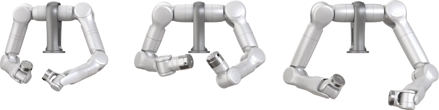
Marvin is a force-controlled humanoid dual-arm system: two 7-DoF arms driven by a single dual-arm controller. The arms are usually mounted on a humanoid torso and support mounting at any angle. Every joint has a built-in torque sensor, and the arms support position and impedance control.
Marvin is not the same as Marvin Pro. Marvin is delivered as arms plus optional modules, and the integrator completes mounting, power, and system-level safety. Marvin Pro is a complete platform with a fixed stand and integrated electrical cabinet.
Models covered
The Marvin Series Robot User Manual V2.2 covers these models:
| Model | Wrist | Max. payload | Max. reach |
|---|---|---|---|
| Marvin M6-CCS | Crossed-axis wrist (CCS) | 6 kg | 696 mm |
| Marvin M6-SRS | Traditional collaborative wrist (SRS) | 6 kg | 686 mm |
| Marvin M3-CCS | Crossed-axis wrist (CCS) | 3 kg | 615 mm |
The product brochure also lists M6S CCS-809, M6S Lite, M3S Long, and M20S models. They are not covered by the V2.2 manual. Confirm the applicable documents with Gento before installing or wiring them.
What's in the box
| Item | Contents | Supply |
|---|---|---|
| Arms | One left arm, one right arm | Standard |
| Controller module | Controller box (main board, regeneration module, braking resistor), power adapter, extension cable kit, E-stop box, two end 8-pin plugs | Optional |
| Power module | Switching power supply (MEAN WELL RSP-2000-48) and power cable | Optional |
| Robot stand | Stand with mounting screws | Optional |
| Robot base | Base | Optional |
The arms are not packed in a fixed position. Tell them apart by the label at the base and the letter laser-marked on the end flange: "L" for the left arm, "R" for the right arm.
According to the product brochure, if these modules are not ordered, the customer provides the arm power supply and the host computer.
Intended use and limits
Marvin is designed for human-robot collaboration. Tools, workpieces, equipment, and the surroundings all need a complete risk assessment. The following uses are not permitted:
- Environments with dust or other explosion risks
- Life-critical applications
- Use without hazard analysis and risk assessment, or after a failed risk assessment
- Operation outside the permitted operating parameters
Next steps
- Check the specifications and identify your model.
- Mount the arms following handling & installation.
- Connect power, communication, and the E-stop following wiring.
- Connect the host software and read status.
Manuals and product documents are listed in manuals & source resources.