Interfaces & power
Rear interfaces
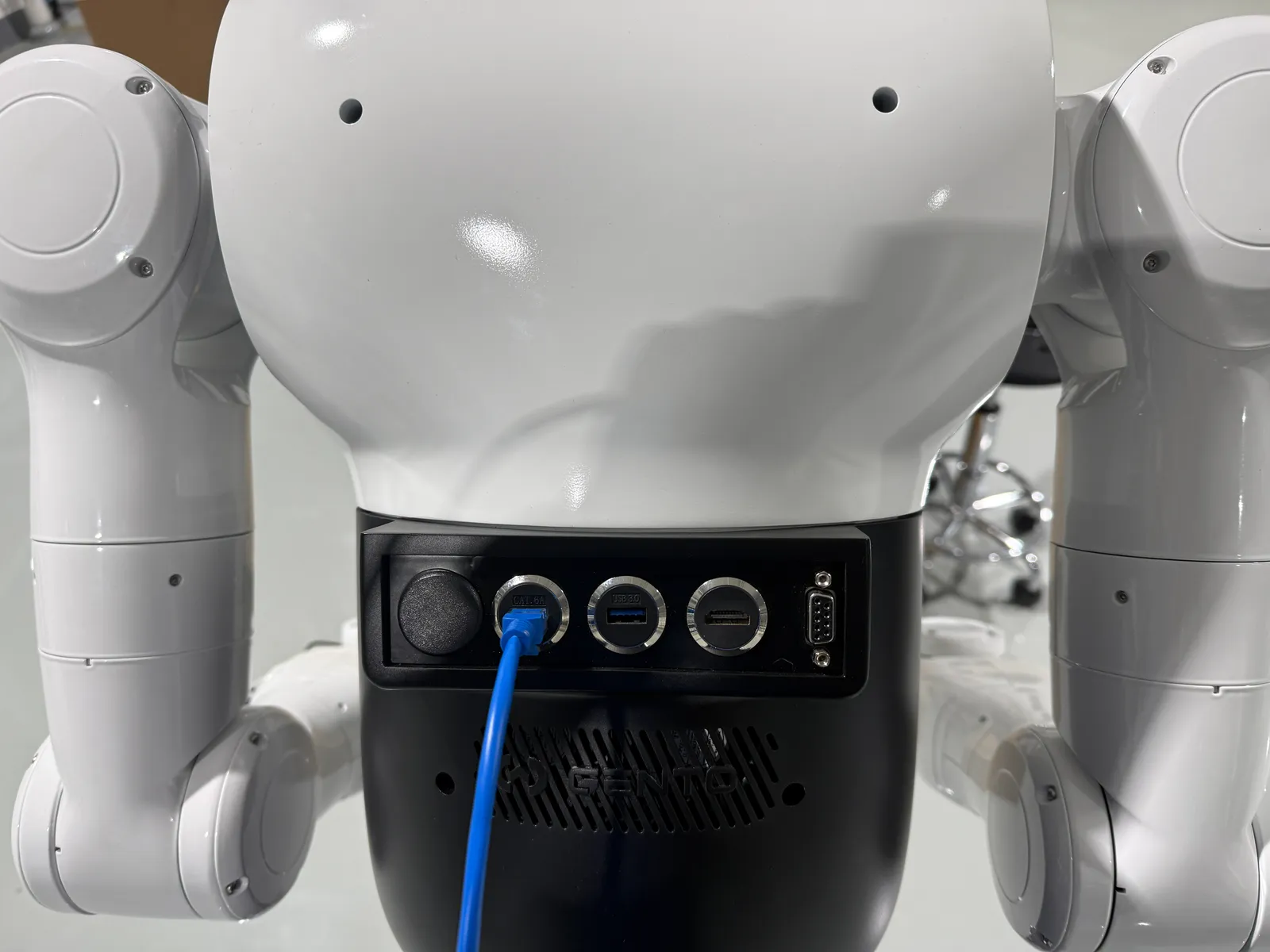
The rear panel carries the Ethernet ports used for the host PC and teleoperation network. Follow the labels on your delivered robot.
Arm end 8-pin interface
The end flange of each Marvin arm has an 8-pin connector for tool power and communication.
| Pins | Function |
|---|---|
| 1 / 2 | DC 24 V power output, 3 A rated |
| 3 / 4 | RS-485 channel 1 |
| 5 / 6 | RS-485 channel 2 |
| 7 / 8 | CAN, CAN FD by default |
To test the RS-485 and CAN channels, use the CAN/485 tool in GentoPlatform. COM1 and COM2 are RS-485 channels 1 and 2.
Network
Skye uses the same robot network as the other Gento robots:
| Device | IP address |
|---|---|
| AI computer (Orin or Thor) | 6.6.7.100 |
| x86 motion controller | 6.6.7.190 |
Set your computer to an address on the 6.6.7.x subnet. For step-by-step setup, see Connect your PC. To log in to the Orin or Thor, see Connect to the Orin or Thor.
Chassis communication (ROS 2)
The chassis talks to your computer over ROS 2. In a distributed ROS 2 system, all nodes in the same DDS domain are equal peers. As long as the network is connected, the domain IDs match, and the nodes can discover each other, nodes on your computer can publish commands, call services, and send action goals, and the robot's ROS 2 interfaces respond to standard messages.
Choose the DDS implementation on your computer with the RMW_IMPLEMENTATION environment variable:
| DDS | Characteristics | Typical use |
|---|---|---|
| Fast DDS | Open source, the recommended default; shared-memory optimization and low latency | Most robot applications, especially with strict real-time requirements |
| Cyclone DDS | Lightweight, with low resource usage | Small robots and edge computing devices |
export ROS_DOMAIN_ID=<the robot's domain ID>
export RMW_IMPLEMENTATION=rmw_fastrtps_cpp     # Fast DDS
# export RMW_IMPLEMENTATION=rmw_cyclonedds_cpp # Cyclone DDS
Topic, service, and action names for the chassis are in the chassis interface documentation supplied with the robot.
Power
Power by component
| Component | Supply | Power |
|---|---|---|
| Motherboard | DC 12 V | 20 W |
| Left arm (M6) | DC 48 V ±20% | 300 W typical, 600 W peak |
| Right arm (M6) | DC 48 V ±20% | 300 W typical, 600 W peak |
The arm servo drives report an overvoltage error above 58 V and an undervoltage error below 30 V.
Main controller power supply
| Parameter | Value |
|---|---|
| Rated voltage | 24 V DC |
| Input voltage range | 9–36 V |
| Rated current | 2.5 A recommended (24 V supply) |
| Power consumption | Below 80 W in typical use |
| Start-up | Starts automatically on power-up (default) |
| Protection | Undervoltage, overvoltage, overcurrent, and reverse polarity |
| Peripheral power | USB 3.0: 5 V, 2 A per port. GMSL1/2: 12 V, 0.4 A per port. The network ports are not powered |
Power board connectors
| Connector | Pin 1 | Pin 2 | Nominal voltage | Pulse voltage |
|---|---|---|---|---|
| X6 (48 V output 1) | 48V+ | GND | 48 V | Below 70 V |
| X7 (48 V output 2) | 48V+ | GND | 48 V | Below 70 V |
| X8 (48 V output 3) | 48V+ | GND | 48 V | Below 70 V |
| X9 (24 V) | VCC_24V | GND | 24 V | — |
The power board also has two reserved external signal interfaces (CANH and CANL), a 10-pin I/O connector (RS-485 485A1/485B1, inputs IN1, IN3, and IN4, outputs OUT2–OUT5), and a connector with STOP_IN, 24 V, and GND. Section 3.1.7 of the manual shows where each connector is.
Next: software, SDK & teleoperation.
Teleoperation network
For Apex teleoperation, the robot's onboard controller (Tianzhun 003 or Lingjing Thor) is at 6.6.7.100 by default. Connect the robot's rear Ethernet port, the host PC, and the headset (through its Type-C Ethernet adapter) to the same router or switch, on the same subnet, with no two devices sharing an address.
Use port 1 with a Tianzhun controller and port 2 with a Lingjing Thor controller. Don't swap them.
For the wiring steps and checks, see Skye and Luna: first teleoperation.